The Audi ignition coil I wanted to fit to the Golf engine has caused lots & lots of head scratching. The main reason for fitting it
was to tidy up the engine bay as the coil bolts straight to the cam cover of VAG 20 valve engines, replacing the messy setup I had
fitted which used HT leads not available off the shelf. Also, I don't believe anyone has controlled this type
of coil with megasquirt before which made it more appealing! The coil was fitted to the Audi A4 1.8 20v non-turbo model from
around 1996 to 1999, also possibly some VW Passat's, engine code ADR and AFY. Audi part number 058905101A, Bosch no 191853817c,
Eurocarparts no 413440130. The cam cover of the ADR engine is slightly different to the AGU - the plug holes are smaller & it has
no oil breather take off. The BAM cover may be different again, not confirmed.

Replacement coil

Fitted to the engine

Factory wiring diagram |
|
It looks like any other wasted spark coil pack, although has a large heatsink on top. All the
wasted spark coils I've seen have 3 pins, a 12v supply (usually the centre pin) and 1 other pin for each
coil which is earthed by the ECU. Studying the factory wiring diagram showed nothing unexpected, the only unusual feature was a
seperate earth point on the side of the ignition coil, yet various testing with 4
different coils (including 1 brand new) I couldn't get them to work. I stumbled on this snippet of info on the vems.hu website.
"pin2=+12V, 15A fuse recommended, pin4=GND, pin1 and pin3 are logiclevel inputs.", although it listed a different part number.
I bench tested one & used a 5v supply instead of an earth to trigger the coils & it worked! Some coil
on plug (COP) fitments also trigger with a 5v or 12v feed.

Coil pinouts

Testing the coil
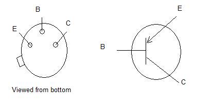
The new transistors must be fitted in the correct orientation, the 3 pins are the base, collector and emitter, a metal tag
is usually next to the emitter. The picture shows a PNP transistor.
|
|
Both VB921 transistors were removed from the megasquirt ECU. I had one wired to IGN, pin 36 and the other to IAC2B, pin 31.
The megamanual for the V3.0 ECU shows the second VB921 wired into SPR4, pin 6, perhaps it was different when I originally wired
mine up? The new transistor circuits were fitted in the prototype section of the ECU. The 1K resistors fitted between R26 & R29
respectively, 5v supply taken from the proto area and the outputs connected to IGN & IAC2B, as per the
old outputs.
Megatune settings.
DO NOT CONNECT THE COIL YET! Set spark output not inverted first.
The dwell setting is very important, too much and the coils could become overheated,
too little and there may not be enough
energy to provide a decent spark at high RPM. It can be tested but as I don't have the equipment to measure it, I'll be using
the best guess method. My current settings are Cranking - 5.0 Running - 3.0 Discharge - 0.1
Explanation of terms
Wasted spark - the coilpack
consists of 2 coils and each one has 2 outputs for 2 spark plugs. So evertime each coil fired 2 sparkplugs will spark. These are
paired (on a 4 cylinder engine) 1&4 and 2&3. So when cylinder 1 is on its firing stroke cyl 4 is on its exhaust stroke, hence the
spark is wasted. A 6 cylinder engine will have 3 coils, 8 cyl will have 4 etc.
Dwell - this is a measurement of the time the coil has to charge. In the old days of points & distributors it was measured in degrees.
With distributorless ignition systems is is generally measured in milliseconds. One issue that affects dwell is engine speed,
at low RPM the coil has plenty of time to charge (around 16ms at 1000rpm), as speed increases the saturation time decreases (around
6ms at 3000rpm) which can weaken the spark. Most coils will operate between 2ms and 4ms.
Coil on plug (or COP) - refers to each spark plug having its own coil, usually sitting on top of the plug. This allows the ECU to
control each spark individually, can increase power & reduce emmissions. |
|


